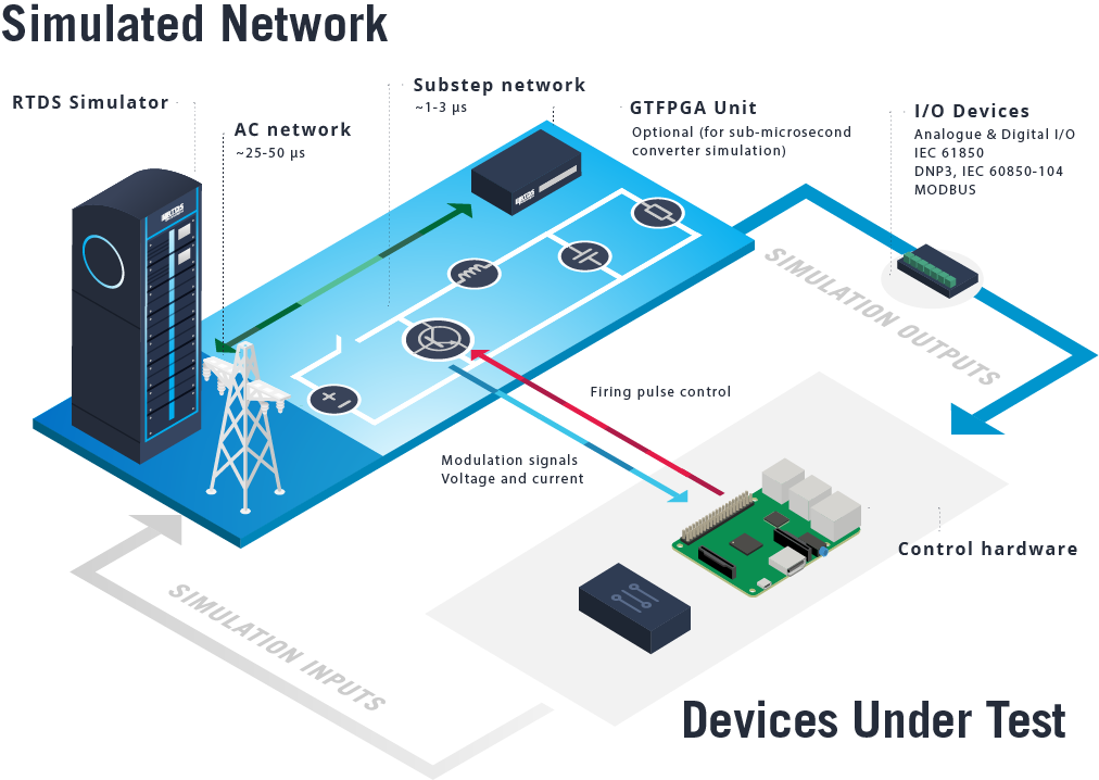
Power electronics-based schemes require small simulation timesteps to properly represent high frequency switching and circuit dynamics. The RTDS® Simulator is designed to achieve extremely small timesteps, allowing engineers to flexibly model the behaviour of power electronics (and the AC network) over a large frequency range in real time. Real control hardware can then be connected to the simulated network and tested to significantly reduce risk and improve performance prior to deployment.
HOW SUBSTEP WORKS
- Power electronic models (consisting of user-configured individual switching elements or set topology models) are created in the RTDS Simulator’s Substep environment, where they run at timesteps a fraction of the size of the main simulation timestep.
- Data is exchanged between the Substep subnetwork and the main network every main timestep, allowing the user to study the interactions between power electronics and the AC network.
- Multiple Substep networks can be connected to represent large power electronic circuits.
In addition to power electronic components, substep networks can also contain any standard AC network component, which will then execute at the substep, rather than the main simulation timestep.

SUBSTEP ADVANTAGE: POWER ELECTRONIC MODELS RUN DIRECTLY ON THE MAIN PROCESSING HARDWARE
The RTDS Simulator’s power electronic models run directly on NovaCor, the simulator’s main processing hardware, rather than external FPGA-based hardware additions. Running power electronics directly on the same powerful multicore processor, and with the same software package, that handles the main network simulation has advantages.
- No additional cost to model power electronics.
- Ease of use for both hardware and software — no need to program/interface an FPGA or gain familiarity with a new software tool.
- No concerns regarding simulation stability or accuracy due to the existence of a hardware interface.
SUBSTEP ADVANTAGE: RESISTIVE SWITCHING ELIMINATES ARTIFICIAL LOSSES AND REDUCES NOISE
The Substep environment contains a selection of fixed-topology converter models that are based on an innovative predictive switching algorithm. These models represent changes in state using a switched resistance (rather than inductance or capacitance, as is the case in L/C switched models).
Models using L/C associated discrete circuits may result in unrealistic artificial power loss as well as fictitious current oscillations leading to noise in the simulation results. The Substep environment and its predictive switching feature have been designed to eliminate these issues for the user.
- Switch at higher frequencies — Substep eliminates artificial losses.
- More accurate results — Substep reduces current/voltage oscillation-induced noise on the waveforms.

Switching represented by switched resistance (predictive switching algorithm)

Switching represented by L/C associated discrete circuits
MODELS AVAILABLE IN THE SUBSTEP ENVIRONMENT
- Common converter topologies with resistive switching (2- and 3-level VSCs including T-type and NPC configurations, buck and boost converters).
- Freely configurable power electronics (individual switching components).
- Point-to-point and back-to-back VSCs.
- MMC valve and control models.
- Firing pulse and ramp generators.
- Lines, machines, transformers, and loads for full circuit simulation.
POPULAR POWER ELECTRONICS APPLICATIONS
Distributed Energy Resources: Simulate two- and three-level converters switched at frequencies in the tens of kHz range and test control or power hardware in the loop with the simulation.
HVDC and FACTS: Simulate LCC, VSC, and MMC-based schemes and comprehensively test the controls for complex systems throughout development and prior to commissioning.
Drives: Simulate custom-topology converters at sub-microsecond timesteps and test their controls in the loop with the simulation.
