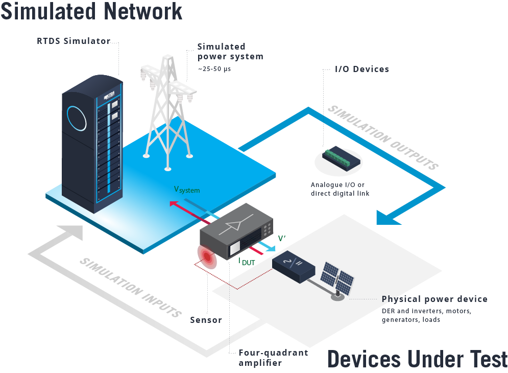
Power-hardware-in-the-loop projects involve the real-time simulation environment exchanging power with real, physical power hardware, such as renewable energy hardware, electric vehicles, batteries, motors and loads. PHIL testing with the RTDS® Simulator allows the engineer to characterize the behaviour of power hardware and de-risk the deployment of novel devices or schemes in the safety of a laboratory.
- DER inverter testing and characterization
- High-credibility AC system behaviour studies
- Electric ship propulsion motor testing

In this simulated network above, the PHIL interface can be created using analogue inputs and outputs, as shown here, or with a direct digital link as described below.
CONSIDERATIONS FOR DEVELOPING A PHIL INTERFACE
Though many successful PHIL projects have been carried out worldwide, developing a valid PHIL interface is not trivial. Technical considerations for a stable and accurate interface include:
- Time delay due to digital/analogue conversion, signal propagation, amplifier response characteristic, and simulation timestep
- Variance in time delay due to test conditions and frequency
- Impedance ratio between device under test and simulated network
- Noise reduction via filters (introduces delay and frequency-dependent magnitude attenuation)
- Selection of an appropriate four-quadrant amplifier
Loop delay and impedance ratio should be quantified and compared to stability criteria when possible in order to validate the PHIL interface.
FOUR-QUADRANT AMPLIFIERS: COMPLETING THE PHIL TESTBED
PHIL requires a four-quadrant amplifier, which can both source and sink real and reactive power, to be placed between the real-time simulator and the power device being tested. The RTDS Simulator has been successfully connected to four-quadrant amplifiers from many different third-party manufacturers. These amplifiers can represent a financial and technical investment of their own, and are selected based on a variety of factors:
- Linear vs. switched-mode operation type
- Source and sink power ratings
- Frequency bandwidth
- Response time and slew rate
- Harmonic distortion and frequency resolution
- Interface connections – conventional analogue or direct digital
- Closed-loop testing of controls for a Modular Stacked DC system for long distance subsea applications
THE RTDS SIMULATOR’S CUSTOM-BUILT AMPLIFIER INTERFACE MODELS
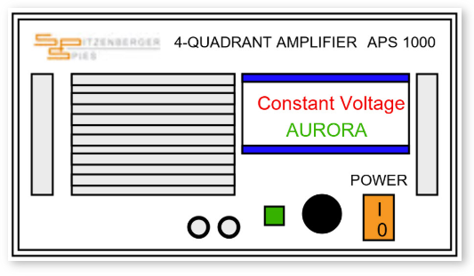
RTDS Technologies has worked alongside amplifier manufacturers to create a custom direct digital interface, allowing the RTDS Simulator to be connected to the amplifier without the use of analogue input and output. Instead, a fibre optic cable is used for bidirectional data exchange via the Aurora communication protocol. This minimizes delays and noise while reducing the complexity and cost of creating a PHIL interface.

This simulation component establishes a convenient Aurora link between the simulator and amplifier. It also includes embedded voltage and current sources to increase ease of use.
We’re proud to have developed digital interfaces with the following manufacturers:


PHIL SUPPORT FROM RTDS TECHNOLOGIES
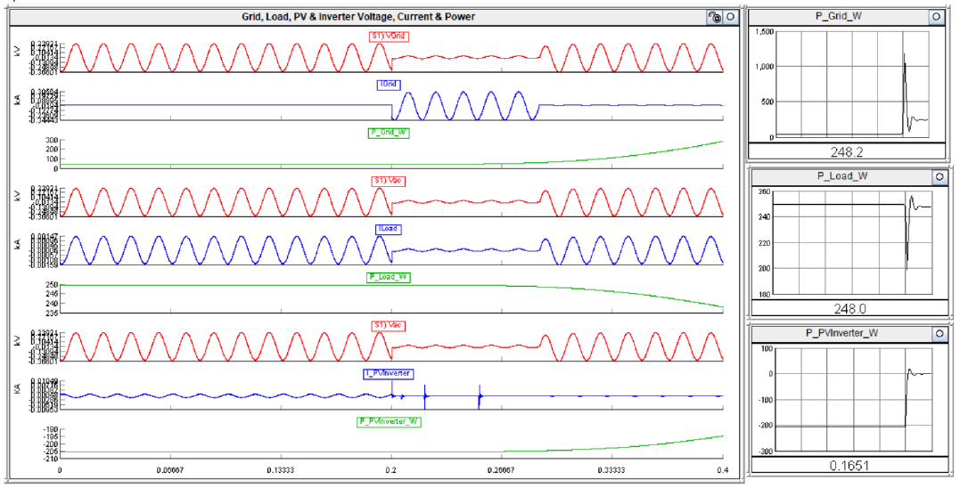
The team behind the RTDS Simulator is dedicated to equipping users with the simulation support, models, and sample cases they need to develop a successful PHIL interface. Users have access to a report detailing our inhouse PHIL experiments with a solar panel and microinverter, including the amplifier selection process, simulation case, interface methodology, and considerations for stability and delay.

Simulation results for power-hardware-in-the-loop testing of a PV microinverter for a 5 cycle L-G fault
